Technical Articles & News

Custom Battery Pack Insights & Resources

Industry knowledge, engineering insights, and technical advice from the Emerging Power team.

0%

Smart RRC Battery Packs are more than portable energy containers for medical and professional equipment. They combine rechargeable cells, protection circuits, fuel gauging, communication, and controlled charging. The result is a battery that can report its condition, not merely deliver power.

This distinction matters in hospitals, field-service kits, and compact diagnostic devices. A technician may see remaining capacity, cycle history, temperature, and fault alerts before a device shuts down. Small details matter. A reliable gauge can prevent an unexpected interruption during patient monitoring or equipment maintenance. However, “smart” does not automatically mean safer or more accurate. Poor calibration, aging cells, heat, and unsuitable chargers can still create misleading readings.

Industry research supports this shift toward intelligent battery management. MarketsandMarkets identifies battery management systems as a fast-growing technology market, driven by safety, monitoring, and the wider adoption of rechargeable equipment. IDTechEx’s Battery Management Systems research also highlights the growing role of data-driven diagnostics and state-of-health estimation. These reports cover broader battery applications, not only RRC formats, so their figures should not be treated as direct forecasts for one product category. That limitation deserves attention.

Standards remain important. IEC 62133-2 addresses safety requirements for portable sealed secondary cells and batteries. UN 38.3 testing supports safer transportation of lithium battery products. Yet compliance documents cannot replace practical validation. Engineers still need to examine thermal behavior, connector reliability, charging cycles, and real-world runtime. This article explains what Smart RRC Battery Packs are, how their internal intelligence works, and where their benefits may stop. Information is valuable. Verified performance is better.
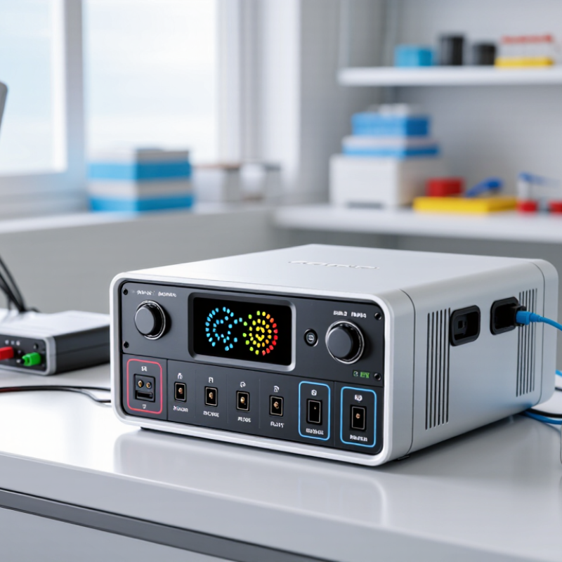
What Is a Smart RRC Battery Pack?

Definition: What Makes an RRC Battery Pack “Smart”?

What Is a Smart RRC Battery Pack?

A smart RRC battery pack contains more than cells, wiring, and a connector. Its battery management system measures voltage, current, temperature, and charging status. It can share this information with a host device through a digital communication interface. That data supports safer charging, clearer maintenance, and more accurate remaining-capacity estimates. However, “smart” is not a magic label. A weak sensor, poor calibration, or outdated firmware can still produce misleading readings.

The International Energy Agency reported that global electric car sales exceeded 17 million in 2024. This growth increases demand for dependable battery monitoring across portable and industrial equipment. In a smart RRC pack, protection circuits can disconnect the output during abnormal temperature, overcurrent, or deep discharge conditions. Many designs also record cycle history and estimate battery health. These functions help technicians replace packs before unexpected shutdowns occur. Yet, capacity estimates are not perfect. They change with age, load, temperature, and charging habits. That limitation deserves attention.

Tips: Ask for measurable functions, not marketing language. Check whether the pack reports voltage, temperature, state of charge, and fault events. Confirm communication compatibility with the host system. Review safety testing against applicable standards, such as IEC 62133-2. Keep charging records. They reveal problems early. A smart pack still needs human judgment.

Core Architecture: Cells, BMS, Fuel Gauge, and Communication Interface

What Is a Smart RRC Battery Pack?

Core Architecture: Cells, BMS, Fuel Gauge, and Communication Interface

A smart RRC battery pack is more than a group of rechargeable cells. Its performance depends on how the cells, control electronics, and host device work together. Inside, cells are arranged in series, parallel groups, or both. This configuration sets the pack’s voltage, capacity, and current capability. Mechanical spacing also matters. Poor contact pressure can create heat and unstable readings.

The battery management system, or BMS, monitors cell voltage, pack current, and temperature. It can stop charging or discharging when conditions become unsafe. It also balances cells during charging, although balancing is often slower than users expect. Protection is essential. Still, a BMS cannot repair damaged cells or compensate for poor wiring. That limitation deserves attention.

A fuel gauge estimates remaining capacity and battery health. It combines current measurements, voltage behavior, temperature, and learned charge cycles. Voltage alone can mislead, especially under heavy load. The communication interface transfers this information to the host device. Common options include SMBus, I²C, or other defined serial protocols. The host may request voltage, current, temperature, cycle count, and fault status. During service testing, I compare reported values with calibrated instruments. Small differences are normal. Large differences may indicate calibration drift, connector resistance, or aging cells. A perfect estimate is unrealistic. Reliable packs need tested cells, validated firmware, and clear fault reporting.

What Is a Smart RRC Battery Pack? - Core Architecture: Cells, BMS, Fuel Gauge, and Communication Interface

Architecture Element Primary Function Typical Technical Characteristics Key Measurements or Data Design Considerations
Lithium-Ion Cell Array Stores and delivers electrical energy to the host device. A common rechargeable lithium-ion cell has a nominal voltage of approximately 3.6–3.7 V and a full-charge voltage commonly near 4.2 V. Cells may be connected in series for higher voltage and in parallel for higher capacity. Pack voltage, current, capacity in Ah, energy in Wh, cell voltage, cell temperature, cycle count, and impedance-related indicators. Cells should be matched for capacity, impedance, age, and state of charge. Mechanical compression, insulation, thermal spacing, and short-circuit protection are essential.
Series and Parallel Configuration Sets the pack voltage, capacity, current capability, and stored energy. For a 3-series configuration, the nominal pack voltage is approximately 10.8–11.1 V and the full-charge voltage is commonly about 12.6 V when using 4.2 V maximum cells. Series count, parallel count, nominal voltage, maximum charge voltage, minimum discharge voltage, rated capacity, and continuous or peak current. The charger must match the series count and cell chemistry. The protection system must monitor individual series groups rather than only total pack voltage.
Battery Management System (BMS) Monitors, protects, and manages the cell array during charging, discharging, storage, and fault conditions. Usually includes voltage-monitoring circuitry, a microcontroller, current sensing, temperature inputs, switching devices, nonvolatile memory, and protection logic. Overvoltage, undervoltage, overcurrent, short circuit, overtemperature, undertemperature, charge permission, discharge permission, and fault status. Protection thresholds must be selected according to the cell manufacturer's limits. Hardware protection is normally used as a secondary safety layer to firmware control.
Cell Balancing Circuit Reduces differences in state of charge between series-connected cells. Passive balancing is common and dissipates excess energy through resistors. Active balancing transfers energy between cells and can improve efficiency but adds complexity. Individual cell voltage difference, balancing start voltage, balancing current, balancing duration, and balancing fault status. Balancing settings should account for cell chemistry, pack configuration, thermal conditions, and the expected storage period.
Current-Sensing Element Measures charge and discharge current for protection and battery-state estimation. A low-resistance shunt is widely used for accurate current measurement. Hall-effect sensing may provide electrical isolation and lower insertion loss in some designs. Instantaneous current, accumulated charge, peak current, overcurrent duration, and charge or discharge direction. Shunt tolerance, temperature coefficient, amplifier offset, sampling rate, and power dissipation affect measurement accuracy.
Temperature-Sensing Network Detects unsafe thermal conditions and supports temperature-compensated charging and capacity estimation. Negative-temperature-coefficient thermistors are commonly placed near cells, power switches, and other heat-producing areas. Cell temperature, board temperature, charge-temperature permission, discharge-temperature permission, and thermal fault status. Sensor placement should reflect the hottest realistic locations. Charging and discharging temperature limits may be different.
Protection Switches Disconnect the battery from the external terminals when a hazardous electrical condition is detected. Back-to-back MOSFETs are commonly used to control charge and discharge paths while limiting reverse-current flow. Charge FET state, discharge FET state, gate-drive fault, pack current, and protection-trip reason. The switches must withstand the maximum pack voltage, peak current, inrush current, and fault energy with suitable thermal margins.
Fuel Gauge Estimates remaining charge, available energy, battery health, and operating time. Typically combines coulomb counting with voltage, current, temperature, impedance, and battery-learning data. It may be integrated into the BMS controller or implemented as a dedicated circuit. State of charge, state of health, remaining capacity, full-charge capacity, cycle count, time to empty, time to full, and battery voltage. Accuracy depends on current-sensor calibration, measurement drift, cell aging, temperature, charge termination behavior, and periodic synchronization.
Microcontroller and Firmware Executes monitoring, estimation, protection, diagnostics, logging, and communication functions. Firmware commonly applies filtering, fault timers, state machines, calibration constants, charge-control rules, and event logging. Firmware version, fault history, calibration data, reset reason, operating hours, cycle count, and service information. Safety-related firmware should use defined fault responses, watchdog supervision, robust data integrity checks, and controlled update procedures.
Communication Interface Exchanges battery status, limits, warnings, authentication data, and diagnostic information with the host device or charger. Common wired interfaces include SMBus or I²C. UART, CAN, or other protocols may be used when required by the system architecture. Voltage, current, temperature, state of charge, state of health, remaining capacity, charge current limit, charge voltage limit, and alarm codes. The host protocol should define address allocation, timing, error detection, timeout behavior, data units, endianness, and safe behavior after communication loss.
Nonvolatile Memory Stores calibration values, learned battery parameters, production data, and fault history when required. May be integrated into the controller or provided through electrically erasable memory with data-retention and write-cycle limits. Design capacity, full-charge capacity, cycle count, calibration coefficients, manufacturing date code, and permanent fault records. Critical records should use checksums or error-correcting methods, controlled write intervals, and protection against incomplete updates.
External Terminals and Mechanical Housing Provides safe power, signal, mechanical retention, and environmental protection between the battery pack and host device. May include positive and negative power terminals, communication pins, thermistor contacts, keying features, seals, and service or identification contacts. Terminal voltage, contact resistance, connector temperature, insertion-cycle rating, ingress protection, and mechanical latch status. The enclosure must control movement, prevent abrasion and short circuits, support heat dissipation, and maintain reliable contact under vibration.
Typical Smart-Pack Data Flow: The cell array provides energy; voltage, current, and temperature sensors collect operating data; the BMS applies protection and control logic; the fuel gauge estimates remaining capacity and battery health; and the communication interface reports limits, status, and faults to the host system.

Battery Intelligence: How SMBus Reports Voltage, Current, and State of Charge

What Is a Smart RRC Battery Pack?

Battery Intelligence: How SMBus Reports Voltage, Current, and State of Charge

A smart RRC battery pack combines cells, protection circuits, sensors, and a communication controller. Through the SMBus interface, the pack reports live operating data to the host device. Voltage readings show the pack’s electrical pressure. Current readings indicate whether energy is entering or leaving the cells. Many systems also report temperature, cycle count, and charging status.

The data appears in defined registers, often as measured values with specific units. A service technician can compare the reported voltage with a multimeter reading during a controlled bench test. Small differences may reveal wiring resistance, sensor tolerance, or timing delays. State of charge is more complicated. The controller estimates it from voltage, current flow, temperature, and stored capacity. It is not a direct fuel gauge.

Load changes can make the displayed percentage move slowly or briefly appear inconsistent. Aging cells create another problem. The original capacity value may no longer match real performance. Calibration helps, but it cannot correct every imbalance. I have found that reviewing current direction and temperature often explains confusing readings faster than checking voltage alone. Still, SMBus data should be validated against safe test conditions and the pack’s technical documentation. Mistakes happen. A reliable reading needs context.

Safety Framework: IEC 62133-2, UN 38.3, and Multi-Layer Protection

What Is a Smart RRC Battery Pack?

A smart RRC battery pack combines rechargeable cells with monitoring electronics, protection circuits, and communication functions. Its controller tracks voltage, current, temperature, and charging cycles. Small sensors matter. A warm cell can change the safety decision within seconds.

The safety framework begins with IEC 62133-2, which evaluates rechargeable lithium cells and batteries under electrical, mechanical, and environmental stresses. Testing can include external short circuits, abnormal charging, vibration, and forced discharge. UN 38.3 adds transport-focused testing, including altitude simulation, thermal cycling, vibration, shock, and short-circuit checks. These requirements are practical, not decorative. The International Energy Agency reported that global battery demand for electric vehicles exceeded 750 GWh in 2023, showing why consistent safety controls matter across growing supply chains.

A well-designed pack also uses multiple protection layers. A primary circuit limits overcharge and over-discharge. A secondary cutoff can isolate the pack during a serious fault. Thermal sensors, cell balancing, insulation, flame-resistant housing, and controlled charging add further barriers. Firmware should record abnormal events and support traceable inspection. Still, certification does not guarantee perfect field behavior. Aging, damaged connectors, poor storage, or inaccurate temperature readings can defeat a good design. That uncomfortable gap deserves attention. Safety depends on testing, manufacturing discipline, and honest maintenance records.

What Is a Smart RRC Battery Pack?

Safety Framework: IEC 62133-2, UN 38.3, and Multi-Layer Protection

IEC 62133-2

Addresses safety requirements and testing for portable sealed secondary lithium cells and batteries under intended use and reasonably foreseeable misuse.

UN 38.3

Covers the transport test sequence for lithium cells and batteries, including altitude, thermal, vibration, shock, short-circuit, impact or crush, overcharge, and forced-discharge tests.

Multi-Layer Protection

A smart pack typically combines cell-level safeguards, battery-management controls, electrical isolation, mechanical protection, and validated transport compliance.

The chart shows the eight named UN 38.3 test categories in sequence. The bar height represents the test sequence position, not a risk score, pass threshold, or severity ranking. Actual acceptance criteria depend on the applicable edition, cell chemistry, battery design, and test configuration.

Performance Metrics: Energy Density, Cycle Life, and Operating Temperature Ranges

What Is a Smart RRC Battery Pack?

A smart RRC battery pack combines rechargeable cells, protection circuits, fuel gauging, and digital communication. It reports voltage, current, temperature, state of charge, and aging data. This intelligence matters because displayed capacity can drift. A pack showing 80% may not deliver 80% under heavy load. Tiny screens can mislead.

Energy density affects weight, runtime, and enclosure size. The IEA’s Global EV Outlook 2024 reports leading lithium-ion cells approaching 250 Wh/kg. DOE’s Battery500 program uses 500 Wh/kg as a development target, not a normal commercial rating.

Cycle life depends on chemistry, depth of discharge, heat, and charging speed. DOE’s Energy Storage Handbook places many lithium-ion systems near 1,000–3,000 cycles. That range is useful, but imperfect. IEC 62133-2 covers safety testing, not one universal lifespan.

Typical engineering guidance allows charging near 0–45°C and discharging around -20–60°C. Actual limits must come from the pack specification.

Tips: Check energy density at cell or pack level. These numbers are not interchangeable. Ask for cycle-life data at a stated depth of discharge and temperature. Review logged temperature history, not only the battery gauge. If the pack operates near its thermal limits, expect faster aging. A neat spreadsheet still misses real-world vibration, dust, and irregular charging.

FAQS

What is a smart rechargeable battery pack?

It combines rechargeable cells, protection electronics, a fuel gauge, and a digital communication interface. The pack reports operating data to the host device. It is not merely a box of cells.

How do cell arrangements affect battery performance?

Cells connected in series increase voltage. Parallel groups increase capacity and current capability. Mechanical spacing also matters. Weak contact pressure can create heat and unstable readings.

What does the battery management system monitor?

The management system monitors cell voltage, pack current, and temperature. It can stop charging or discharging during unsafe conditions. It may balance cells during charging, but balancing can be slow.

Can the management system repair damaged cells?

No. It provides protection, not repair. It cannot fix damaged cells, poor wiring, or weak connections. That limitation is easy to overlook.

How does the fuel gauge estimate remaining capacity?

It combines current measurements, voltage behavior, temperature, and learned charge cycles. Voltage alone can mislead during heavy loads. A displayed 80% may deliver much less energy.

What information can the host device receive?

The interface may provide voltage, current, temperature, cycle count, and fault status. Service technicians should compare reported values with calibrated instruments. Small differences are normal. Large differences deserve investigation.

What affects energy density and runtime?

Energy density influences pack weight, runtime, and enclosure size. Check whether the figure describes cells or the complete pack. These numbers are not interchangeable.

How long can a rechargeable battery pack last?

Many lithium-based systems reach roughly 1,000 to 3,000 cycles under suitable conditions. Actual life depends on chemistry, discharge depth, heat, and charging speed. The range is useful, but imperfect.

What operating temperatures should users expect?

Typical guidance allows charging near 0–45°C and discharging around -20–60°C. The exact limits belong to the pack specification. Operation near thermal limits can accelerate aging.

How should pack performance be tested?

Review temperature history, cycle conditions, and fault logs. Test voltage and current with calibrated instruments. Vibration, dust, and irregular charging may still expose problems. A clean spreadsheet never tells the whole story.

Conclusion

Smart RRC Battery Packs are rechargeable battery systems designed to do more than store and deliver energy. Their “smart” capability comes from an integrated architecture that combines battery cells, a battery management system (BMS), a fuel gauge, and a communication interface. Together, these components monitor key operating conditions and provide useful information about voltage, current, temperature, remaining capacity, and state of charge. Through communication protocols such as SMBus, the pack can report battery data to a host device, supporting more accurate power management and easier maintenance.

Safety and reliability are also central to the design. Multi-layer protection can help prevent overcharge, over-discharge, excessive current, overheating, and short-circuit conditions. Compliance considerations may include IEC 62133-2 and UN 38.3 testing, depending on the intended application and transportation requirements. Important performance measures include energy density, cycle life, charging efficiency, and operating temperature range. By combining intelligent monitoring with protective controls and measurable performance, Smart RRC Battery Packs offer a dependable power solution for demanding electronic equipment.


Ethan

Ethan

Ethan is a dedicated marketing professional with a strong understanding of the company’s products, services, and market strategy. With a passion for clear communication and practical value, he regularly updates the company website with insightful blog articles that help readers better understand......