Choosing Military Application Battery Packs in 2026 requires more than comparing capacity, voltage, and unit price. A pack may power a soldier-worn radio, an unmanned ground vehicle, or a surveillance sensor in freezing rain. Each mission creates different demands for energy density, shock resistance, thermal control, charging speed, and service life. The correct decision begins with the operating profile, not a catalogue headline.
The International Energy Agency’s Global EV Outlook 2025 reports that annual global battery demand exceeded 1 TWh in 2024. This scale is accelerating investment in lithium-ion cells, manufacturing quality, and critical-mineral security. However, military buyers face harsher conditions than most commercial users. The U.S. Department of Defense Operational Energy Strategy highlights energy resilience, reduced logistics burdens, and dependable power during distributed operations. Those priorities make cell traceability, battery-management software, and safe transport procedures essential evaluation points.
Field reality is less tidy. A high-energy pack can reduce carried weight, yet it may increase thermal-management complexity. A rugged enclosure can protect cells, but it can also add mass and restrict cooling. IDTechEx’s research on batteries for military and security applications emphasizes specialized requirements, including extreme-temperature performance and mission reliability. Still, market forecasts should not replace controlled testing. A promising laboratory result may weaken after repeated drops, salt exposure, or partial charging. That assumption deserves challenge. In this guide, we examine Military Application Battery Packs through measurable criteria, supplier evidence, lifecycle cost, and realistic mission scenarios. Reliability matters more than impressive specifications.
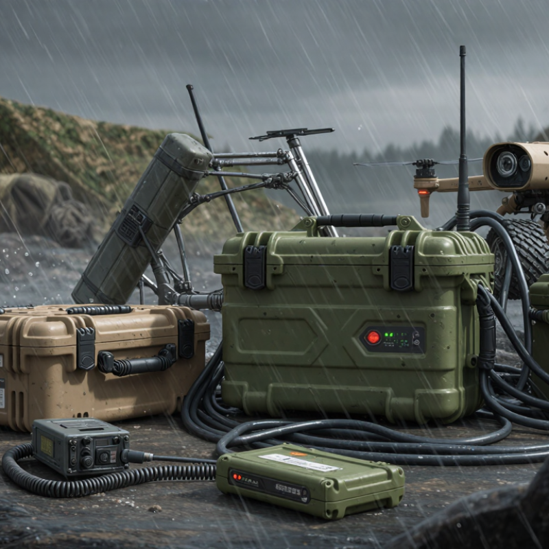
Choosing a military application battery pack in 2026 starts with the mission, not the catalogue. Define the required voltage for radios, sensors, or portable computing equipment. Then estimate runtime under realistic field conditions. A pack rated for ten hours in a laboratory may deliver less in freezing weather. Measure normal consumption, standby draw, and short peak loads separately. Motors, transmitters, and heated systems can demand sudden current spikes. Ignoring these spikes may cause voltage drops or equipment resets.
Tips: Build a simple load table. Record voltage, average watts, peak watts, duty cycle, and expected hours. Add a practical reserve, but avoid excessive capacity. Larger packs increase weight and handling strain. Target 150–250 Wh/kg at the pack level when suitable, not only at the cell level. Enclosure materials, protection circuits, connectors, and thermal controls reduce usable energy density.
Field testing remains essential. I have seen neat spreadsheets fail when cold batteries powered several devices together. Test the complete pack with real cables and simulated peak loads. Check charging time, state-of-charge accuracy, vibration resistance, and safe fault behavior. A pack with excellent energy density can still be a poor choice if operators cannot carry or service it. Requirements may also change after trials. That is normal. Revisit the calculation before procurement, especially when mission duration, weather, or peak equipment loads remain uncertain.
The following planning table uses representative system-level ranges for ruggedized battery-pack sizing. Actual requirements should be verified through measured load profiles, environmental testing, platform integration limits, and applicable safety standards.
| Mission Profile | Typical Equipment | Nominal Pack Voltage | Required Runtime | Continuous Load | Peak Load | Estimated Usable Energy | Target Pack-Level Specific Energy | Primary Selection Considerations |
|---|---|---|---|---|---|---|---|---|
| Dismounted communications and sensing | Portable radios, navigation devices, environmental sensors, data terminals | 12–28 V DC | 8–16 hours | 20–120 W | 150–400 W for short transmit or startup events | 0.3–1.5 kWh | 150–220 Wh/kg | Low mass, quiet operation, hot-swapping, state-of-charge accuracy, and compatibility with regulated DC outputs. |
| Portable surveillance and thermal-imaging systems | Electro-optical payloads, thermal cameras, laser rangefinding and recording equipment | 12–24 V DC | 6–12 hours | 40–180 W | 250–600 W during motor movement, illumination, or data transmission | 0.5–2.2 kWh | 160–230 Wh/kg | Prioritize stable output voltage, low electromagnetic interference, thermal management, and adequate surge-current capability. |
| Portable command and communications relay | Secure networking equipment, signal-processing hardware, antennas, and control electronics | 24–48 V DC | 12–24 hours | 150–600 W | 800–1,500 W during amplifier or computing transients | 3–14 kWh | 170–240 Wh/kg | Use parallel modules where necessary; verify continuous cooling, connector ratings, surge response, and electromagnetic compatibility. |
| Small unmanned aerial system | Electric propulsion, flight computer, navigation, communications, and payload electronics | 22–52 V DC | 45–180 minutes | 500–2,500 W | 1,500–6,000 W during launch, climb, maneuvering, or cold-weather operation | 0.8–7.5 kWh | 180–250 Wh/kg | High discharge capability, vibration resistance, cell balancing, thermal monitoring, and strict mass distribution limits are essential. |
| Unmanned ground vehicle | Electric drive motors, cameras, lidar, onboard computing, and communications equipment | 24–72 V DC | 2–10 hours | 1–8 kW | 3–20 kW during acceleration, obstacle crossing, or grade climbing | 4–60 kWh | 160–230 Wh/kg | Balance specific energy against peak power, shock tolerance, regenerative-braking acceptance, serviceability, and pack isolation. |
| Vehicle auxiliary power | Mission electronics, radios, sensors, computing, refrigeration, and silent-watch loads | 24–96 V DC | 4–16 hours with the main engine off | 1–10 kW | 5–25 kW for equipment startup and transient loads | 8–160 kWh | 150–220 Wh/kg | Confirm integration with the vehicle electrical bus, alternator or charger, fault isolation, enclosure cooling, and maintenance procedures. |
| Remote fixed-site power | Observation equipment, perimeter sensors, communications, edge computing, and lighting | 24–120 V DC or inverter-fed AC | 24–168 hours | 100 W–2 kW | 2–8 kW during generator or inverter startup | 5–300 kWh | 150–210 Wh/kg | Cycle life, calendar life, low-temperature performance, weather sealing, fire containment, and modular replacement may outweigh maximum specific energy. |
Request complete test reports, sample identification, test dates, and laboratory details. Certificates alone are not enough. Check the exact finished pack.
It evaluates selected environmental methods, including vibration, shock, humidity, temperature changes, and dust. It is not one universal approval stamp. Match each method to the mission.
UN 38.3 covers transport-related testing for lithium battery packs. IEC 62133-2 addresses rechargeable battery safety, including abnormal charging and external short circuits. Confirm both reports cover the actual cell layout and protection circuit.
No. It mainly describes dust and water ingress resistance under specific conditions. It does not prove impact, salt fog, chemical, or long-term wear resistance.
Confirm nominal voltage, peak current, connector polarity, and cold-start voltage sag. Measure startup demand directly. The result may surprise your team.
Compare size, weight, power, and lifecycle cost. Record usable energy at 0°C, recharge time, watt-hours per kilogram, and replacement labor. Nominal capacity can mislead.
Use keyed interfaces, captive fasteners, clear indicators, and module-level service records. Test repeated insertion, sealing, vibration, fault isolation, and hot-swap behavior. Keep it practical.
Users may drop a latch, misread a label, or connect parts under stress. Test with gloves and low light. I once trusted nominal capacity too much; mission energy mattered more.
Choosing Military Application Battery Packs in 2026 requires a mission-focused evaluation rather than a one-size-fits-all approach. Start by defining voltage, operating runtime, peak power demands, and acceptable energy density, with 150–250 Wh/kg serving as a practical reference range. Battery chemistry should then be matched to the required balance of energy, safety, temperature tolerance, service life, and transport considerations. Compliance with MIL-STD-810H, UN 38.3, and IEC 62133-2, along with suitable IP-rated protection, helps confirm durability under vibration, shock, moisture, dust, and environmental stress.
Compatibility with 12 V, 24 V, or 28 V systems is equally important, as are SWaP-C factors: size, weight, power, and total cost. Modular designs can simplify field replacement and maintenance. Buyers should also assess BMS telemetry, data protection, cold-weather performance, charging behavior, and lifecycle costs. The best solution delivers dependable power while supporting operational flexibility, safe handling, and predictable long-term performance.